With Time Comes Wisdom
David J. Fish, Senior Vice President, Welker, Inc., USA, provides an overview of LNG sampling systems and their streamlined evolution over recent years.
LNG is natural gas that has been cooled to a liquid state (liquefied) at approximately -260˚F, for shipping and storage. The volume of natural gas in its liquid state is approximately 600 times smaller than its volume in its gaseous state in a natural gas pipeline. LNG = liquefied natural gas. Hugely important to note, it is natural gas in liquid form. It is not a mysterious or unique hydrocarbon. It is natural gas that has been produced in the traditional manner and that has been processed and liquefied for transportation purposes, with the expectation of being vaporised and returned to natural gas for commercial consumption. At -260˚F it is at approximately 600 to 1 in volume. 1 ft3 of LNG is equal to 600 ft3 of natural gas. This makes marine transport feasible and profitable. Hence, when it is vaporised, it will be natural gas again.
The history of sampling
In the late 1970s and early 1980s, LNG sampling became a product line of Welker Engineering Company (known today as Welker, Inc.). Welker was well known in the natural gas sampling arena as the leading innovator of sampling technology, with unique self-purging sample pump designs and constant pressure sample cylinders. Several LNG tankers and a small number of LNG terminals in the US were successfully equipped with Welker LNG systems, which the company had designed essentially around what is now referred to as Figure 2 in ISO-8943.1 It was patterned after the work undertaken to that point by the US National Bureau of Standards and work completed in Japan under H. Tanaka, along with a basic understanding of LNG and the need to revaporise completely in order to take a natural gas sample. ISO‑8943 was not available until 1991.
Shortly thereafter, the LNG market left the US shores and became more of a European and Southeast Asia initiative. As the market increased and the need for systems increased, Welker developed a system that incorporated existing natural gas sampling technology with sample pumps and constant pressure sample cylinders. Through the company’s overseas partners, a large number of these systems were assembled with Welker components and design input in Europe and Southeast Asia, and with the success of the design, it was included in the ISO standard ISO-8943 as Figure 3, which was first published in 1991.1


With the strong return of the LNG market to the US, the American Petroleum Institute’s (API) Committee on Measurement Quality (COMQ) recognised the need for an LNG standard in its portfolio to address new technologies entering the market. With permission from ISO, API used ISO-8943 as the basis for a modified version to the standard, and from 2020 it has been available as API Chapter 8.6.
Along with ISO-8943 and API 8.6, a very valuable document for the LNG measurement world is the GIIGNL LNG Custody Transfer Handbook, latest edition.
It is well known and acknowledged that during the cryogenic process of taking natural gas to LNG, there are impurities and components that are of interest to be removed, and certain process systems monitor for the presence of those and/or the purity level of the LNG. With a different focus, the sampling systems of ISO-8943 and API 8.6 are designed for the revaporisation of the LNG, and on the heating value of the transported product and the commercial value of the shipped and received product via custody transfer.


Previous studies found that accurate and precise composition determination of LNG mixtures (and other cryogenic liquid mixtures) requires a sampling measurement system (SMS) which contains:2
- A sampling probe which draws a sample without altering the composition.
- A sample conditioner which completely vaporises the sample.
- A gas analyser which accurately and precisely analyses the sample.
LNG sampling systems
LNG sampling systems are located at both loading and unloading facilities. What is loaded is compared to what is discharged at the destination. Boil-off gas (BOG) or ageing (BOG during transport) and other aspects of measurement and transportation have an impact on the custody transfer transaction. BOG will typically be the light ends of the product. Having accurate samples at both ends of the LNG sale will increase the validity of the numbers that come from the gas chromatograph. Proper accounting for BOG can be a significant monetary issue and is recognised as a naturally occurring process.
Custody transfer issues most often centre around the quality and quantity of the product. The sampling system is directly connected to the quality concerns. Of the two, quality and quantity, quality is generally the most difficult one to resolve. A well-designed system can reduce those conflicts. A properly designed system should assure the operator that all the LNG sample that has entered the probe tip at the sample point will come out the back end of the system.
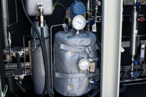
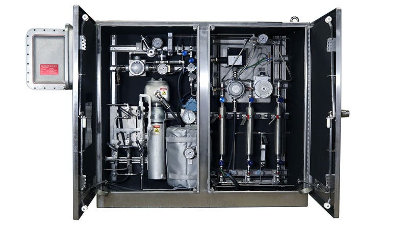
Most typical LNG sampling systems are comprised of a probe to direct the sample flow from the pipeline to the sampling system via specialised tubing runs to maintain the liquid state of the sample. The sampling system is comprised of an inlet check valve; a heated vaporising chamber; an impingement block or device to encourage further vaporisation of any last-minute liquids; an accumulator vessel; outlet regulation and flow control; and sample cylinders or valving direct to the analyser.
Probe importance
As early as 1978, it was understood that the need to keep the LNG sampling line sub-cooled and insulated until it was past the inlet check valve to a system was to prevent premature expansion.2 As soon as LNG begins the revaporising process, and even at a cold temperature, there is the possibility during the natural expansion process that components of interest could be pushed back into the pipeline and not directed through the sampling system to be detected by proper analysis.


It was not until 2012 that technology was available to address that concern. A new probe design with a cryogenic check valve at the point where the LNG sample entered the probe in the pipeline assured that all the sample would only continue to and through the sample system. This eliminated any reverse flow back into the pipeline that would occur with typical probes, and the vaporisation process no longer carried the concern of losing components of the LNG.
The cryogenic LNG sampling probe is a probe with a unique and patented designed check valve at the probe tip. Typical systems have probes, but those probes simply divert LNG out of the pipeline and direct the flow to the sampling system located in a cabinet nearby to the pipeline and sample point. To assure that reverse flow does not occur, the sample lines must be maintained all the way to the entrance of the cabinet and the entrance check valve, at or near -260˚F. If the LNG in the sample line begins to expand due to temperature loss, some components (most likely the heavier components) may be pushed back to the pipeline and lost to the sampling system. The cryogenic probe eliminates that concern, in that when the LNG enters the probe tip, the expansion process – if it occurs prior to reaching the sampling cabinet inlet check valve – will only close the probe tip check and prohibit return to the pipeline. The probe tip check is therefore assuring that all the sample from the pipeline will travel to the sample cabinet, the vaporiser, and ultimately the chromatograph or sample cylinders for the laboratory. Premature vaporisation concerns are removed from the sampling system.
A special container for spot sampling applications has also been developed in recent years for the LNG market. It is designed around the concept of the constant pressure cylinder. Using the flowing LNG present at the sample point, the cylinder is chilled to cryogenic temperatures prior to taking the sample. Acknowledging the expansion factor and the working pressure of the cylinder, a reduced amount of sample is directed into the sample chamber. The contents are transported to a lab where the cylinder is allowed to warm completely, allowing the sample to expand and vaporise in the sample cylinder. During the expansion process, the pre-charge on the cylinder is used as a cushion and slowly bled off, adding volume to the expansion needs. From the cylinder the sample can be injected directly to the analytical device. The user knows that nothing was lost in transfer from the pipeline to the lab. Nothing is left in the tubing, accumulators, heaters, etc. The cylinder will have a special application for special circumstances, but will provide the user with unquestionable integrity regarding the sample taken to the lab.
As technology has improved and innovative and proven designs have entered the market, systems will have variations of the aforementioned systems and improvements. Welker and other sample system manufacturers have designed and streamlined various aspects of LNG sampling during the last 10 – 15 years.
The LNG sampling industry has made significant advances in the last 10 years and the relevant standards and guidelines are being frequently improved to keep up with, and allow for, new technology in the marketplace. System designs and improvements in technology are beginning to allow for reduced size in the process. The fundamental imperative is the total and complete vaporisation of the LNG sample and its delivery to either sample cylinders for laboratory analysis or directed to an on-site gas chromatograph. Size and complexity are not the key – effective and complete vaporisation are. This is where technology has stepped in and made improvements.
As natural gas becomes more and more in demand as a clean burning fuel for home, commercial, and industrial use, the LNG market will increase as a means of transportation and custody transfer for this proven commodity. The quality of the product and the integrity of the measurement of the LNG will continue to be of foremost importance for the LNG market. Improved technology in both the volume measurement (metering) and the quality measurement (sampling) of LNG will serve the industry for years to come.
References
1. ISO-8943 – Refrigerated light hydrocarbon fluids — Sampling of liquefied natural gas — Continuous and intermittent methods – Latest Edition
2. PARRISH, W.R., ARVIDSON, J.M., and LABRECQUE, F.F., 1978, ‘Development and evaluation of an LNG sampling measurement system’. National Bureau of Standards (USA). Thermophysical Properties Div.
