
Techniques of Gas Spot Samples
Purpose
The need to be able to take a representative sample of a hydrocarbon product is necessary to ensure proper accounting for transactions and efficient product processing. Sampling can be accomplished by primarily three techniques: spot, continuous composite or continuous on-line sampling systems. The various spot sampling methods that are available and the implementation of these methods are briefly investigated in this paper, as well as the most appropriate equipment to use.
Introduction
The amount of hydrocarbon product that is transported between producer, processor, distributor and end-user is significant. To be able to verify the exact composition of the product is important from an economic and product treatment standpoint. A small percentage savings made by correctly determining composition will quickly recoup the time and investment made into proper equipment designed to obtain an optimum sample. In addition, if the best sampling procedures are followed, the potential for disputes between supplier and customer will be greatly reduced. The importance of properly determining hydrocarbon gas composition benefits all parties involved and will achieve greater significance as this precious commodity becomes less plentiful and more expensive. The amount of hydrocarbon product that is transported between producer, processor, distributor and user is significant. To be able to verify the exact composition of the product is important from an economic and product treatment standpoint. A small percentage savings made by correctly determining composition will quickly recoup the investment made in the purchase of a system designed to obtain an optimum sample. In addition, if the best sampling procedures are followed, the potential for disputes between supplier and customer will be greatly reduced. The importance of properly determining hydrocarbon gas composition benefits all parties involved and will achieve greater significance as this commodity becomes more widely used in our energy plans and more expensive.
From the Gas Processors Association former individual publication GPA 2166-05, "The objective of the listed sampling procedures is to obtain a representative sample of the gas phase portion of the flowing stream under investigation. Any subsequent analysis of the sample regardless of the accuracy of the analytical procedure, will not reflect the true composition of the flowing stream unless a representative sample is obtained.” And, from current ISO-10715 (2022), a representative sample is, “A sample having the same composition as the natural gas it is attributed to, when the latter is considered as a homogeneous whole.” The current API 14.1/GPA 2166 (2022) offers a similar statement in the latest revision, “Compositionally identical or as near to identical as possible to the sample source stream.” These standards are the most common referenced on Gas Sampling procedures, along with the AGA Gas Measurement Manual, Part No. 11, Section 11.3.
Proper sampling is fundamental to the correct determination of the product composition. In a majority of cases, the sample is also the source for the determination of the specific gravity of the gas. This figure is a critical component of the flow formula, from which we derive the product quantity. An error in sampling effects both quality and quantity, and ultimately, profitability.
Gas Sampling
Natural Gas sampling has been performed for years with techniques handed down from generation to generation. Most of the methods are not sufficient to meet today's requirements of accuracy and repeatability; however, standards have been developed to reach toward these demands. The most widely known standards are GPA-2166-05, API 14.1 and ISO-10715. API had produced a revised API 14.1, of which the latest version was published in May 2016. This standard has generated significant interest in proper sampling techniques, due to a large volume of data produced during the revision work. Work was then focused on activities related combining API 14.1 with GPA-2166. That document was completed and published in September 2022. Also, a complete revision of ISO-10715 was completed and published in October of 2022. It is important that the technician refer to the latest versions of these standards. They are updated for a reason -- IMPROVEMENT!
Measurement technicians or personnel, who will be responsible for physically taking the spot samples, should be fully aware of the importance of their task. They should be knowledgeable of the proper methods, procedures and techniques involved in spot sampling. Periodic training and being updated on revised standards is an important part of their job. Proper performance of their job will have a financial impact on the profits of the company.
A review of relative sampling standards and the operation and installation instructions is an important step the total accurate sampling process. Proper maintenance of all sampling equipment is vital to the operations of all sampling methods. Dirty or poorly maintained sampling apparatus will adversely affect the final results and profitability of the gas company’s operation.
Sampling Components
The different components of a spot sampling system deserve individual consideration, before the various sampling procedures are investigated.
Valves – If shut-off/isolation valves present a restriction that causes a pressure drop, it is possible that condensation could occur due to the chilling from the Joule-Thomson effect. When valves are used on a collection cylinder it is important that there are no leaks from the gland. Light ends will be the first to leak off, thereby causing the sample to be over-represented with heavy ends. It is wise to use valves with soft seals to give a positive shut-off. Large orifice valves should be used, as restrictive valve paths can cause fractionization of the sampled gas.
Filters – The use of a filter in spot sampling procedures is rare and should be done with extreme caution. Proper selection of the filter flow capacity and the particle size capacity should be encouraged. A filter that is too small or does not have a sufficient drip pot capacity for gases that have entrained water, is sure to result in the taking of a bad sample.
Pipe-work – Should be as short and as small a diameter as possible. This will assist in minimizing the time delay from sample point to the cylinder. It will also help maintain the sample integrity.
Heating Elements – There is sufficient evidence to show that when appropriate, heating all components of a sampling system is a prudent step in having a reliable and accurate sampling system. Knowledge of the hydrocarbon dew point of a natural gas stream is a critical issue in obtaining a representative gas sample.
Probes – The correct placement is at the top of the pipe, into the center one third or at least 200 mm (8 inches) for larger diameter pipes; in an area of minimum turbulence, that is, away from headers, bends, valves, etc. Turbulence will stir up the contaminates that usually reside at the bottom of the pipeline and are therefore not normally part of the gas stream. By having the probe at a point of turbulence these contaminates will be taken into the sample, giving a sample that is not representative. The design of the sample probe may vary with tips being beveled, 45°, shrouded, square cut or some other configuration. Testing has been performed to determine whether these designs had any significant impact in the quality of the sample. These tests have proven that in a single-phase gas stream, shape had no impact; but the key is to have the probe in the center of the line in the correct spot (positive velocity/no turbulence) with a proper valve on the outlet. Field applications have shown that mounting the probe on the top of the pipeline is the preferred location. Side or horizontal mounts can easily encourage free liquids (if present) to migrate into the sample system.
Sample Cylinders – Used for the collection of gases and light liquid hydrocarbons, sometimes called "sample bombs". The cylinders come in three forms; (1) One is a plain single cavity cylinder with a valve at each end. This is the most common cylinder and is also known as a spun-end cylinder, constant volume cylinder, or simply as a standard cylinder. The hook up and operation of this cylinder is very straightforward. (2) One is known as a Constant Pressure Sample Cylinder, which takes the form of a closed end cylinder with an internal piston. Before using the Constant Pressure cylinder, one side is pressurized forcing the piston to the sample end. When the sample is taken, the product is then collected and stored at whatever pressure is pre-charged at the back of the piston. Using the Constant Pressure Cylinder, the sample can be collected at a pressure above the vapor pressure of the light ends. By having the piston at the end of the cylinder, the need for excessive purging is eliminated. Pulling a vacuum in the sample cylinder (which is often destroyed by technicians) or using the water outage method is not necessary. It can be guaranteed that the sample taken is composed entirely of the gas being sampled. The hook-up is simple and straightforward making the operation easier for technicians and minimizing the possibility of an incorrect sample being taken. (3) One is a bag lined cylinder designed to provide a disposable liner in a wide mouth, double-ended cylinder enclosure. The liner is collapsed internally with a minor back pressure of Helium or other inert gas or the gas product itself. Purging of the cylinder and bag is not required. The hook-up and operation is simple and straightforward.
Sample cylinders should be constructed with a material that is compatible with the gas. For instance, H2S can be absorbed into the structure of 316 stainless steel. This will necessitate coating the inside of the cylinder Sulfinert® or similar special coating. The resultant sample will not be truly representative otherwise.
Sample cylinders are normally protected with bursting discs. They are less expensive and are lighter weight than relief valves, though their proper selection and replacement should have more importance than is sometimes given them.
With all of the notes on the various components should go the comment which is one of the basic rules of sampling: The materials of construction of the sampling equipment that come into contact with the sample are to be compatible with the product being sampled. It is normally reasonably safe to use 316 stainless steel and Viton elastomeric components. One should look for these materials in selecting equipment and ask questions of suppliers about material selections.
Location and Product
The sample point should be located in a section of the pipeline that always has a positive velocity, a minimum of turbulence, and the tap mounted on top of the pipe. If this simple guideline is followed, it will effectively eliminate meter manifolds, blow down stacks, standby runs, pig traps, headers of all types, drips, or any type of dead-end line.
Also, samples should never be taken around or too close to obstructions, control valves, orifice plates, elbows, tees, or other fittings that might generate aerosols. Free liquids (aerosols) in the stream that may move into the sample cylinder cannot be effectively handled using standard cylinders and conventional methods; however, they may be handled by sampling into the constant pressure cylinder.
An additional major factor in correct sampling procedures is an awareness of the hydrocarbon dew point of the gas stream being sampled. The importance of knowing the HCDP is related to 1). The ambient temperature; 2). The temperature of the equipment being used to collect the sample; and 3). The temperature of the flowing stream. The creation of liquids due to equipment design and equipment temperature must be avoided. Determination of the HCDP of the gas stream can be done by the chilled mirror method or by the use of a number of equation of state models for hydrocarbon dew point determination. There are several programs available such as Peng-Robinson, SRK or Refprop. The variations of the calculated results between different equations of state are so wide, that it is strongly recommended to add 20° to 50°F (11° to 28°C) to the answers. This is to assure the operator that he is designing his sampling system temperature requirements above the actual hydrocarbon dew point of the sampled stream.
Spot Sampling
While there are several methods for spot sampling natural gas, three common methods in use today are the purge, fill and empty method detailed in API 14.1/GPA-2166-2022 section 12.7, the piston cylinder method detailed in section 12.5 and the Helium “Pop” method detailed in section 12.4.
Spot sampling was the primary method of acquiring a sample for analysis until the early 1970's. This method is still widely used today. In today's world of growing trends toward therm-measurement and therm-billing, this method is increasingly expensive in analytical cost and man-hours, as well as a very questionable method of assessing an accurate heating value to volume sales. It is at best a "spot" sample of what was present at the moment the sample was taken. Minutes before and minutes after becoming unknown guesses. While this may be a reasonable risk if the gas source is known by a long historical data base, most gas being consumed today is a combined gas from several origins or is switched from source to source by contractual updates, in some cases by daily or even hourly arrangements. This author has been on location and witnessed a 62 BTU increase at a single sample point, within a one-hour time frame. It was mainly attributed to both a substantial increase and decrease in flow rate as well as well selection changes within the gathering grid. Also, we find typically, that the older the well and the longer it stays in production, the higher the BTU value will become. Natural gas is an extremely fragile product and almost every step in the production, transportation and distribution of natural gas will have an impact on gas quality. Switching wells, pressure changes, temperature changes and storage vessels are only a few of the items that can add or subtract BTU values on the gas moving through measurement stations. Thus, a spot sample may not even represent the correct source in question.
In early years, the spot sampling method was used whereby the gas was introduced into the cylinder until it reached line pressure and then was transported to the laboratory for calorimeter or chromatograph analysis. As the known quality of the gas (BTU value) became more important, tests were conducted to determine if the gas was being altered by the procedure used to fill cylinders. It was determined that contaminates such as air were being introduced to the collected sample and a new filling method was needed. The purge, fill and empty method was adopted and after sometime it was determined that retrograde condensation was occurring by this process and thus a newer method was created. This newer method is known as the GPA method using a manifold and pig tail for filling the Standard Cylinder. This GPA method reduced the negative effects of the "filling only" procedure. The manifold allows gas to be "trapped" in the cylinder at full pressure, rather than simply "dead ended" into the cylinder, i.e., zero pressure up to line pressure. Also, systems with free liquids required special attention and the GPA separator was developed and added to certain techniques.
As the quality of gas became a critical part of billing, along with volume (std. cu. m. or std cu. ft.), the industry again reviewed the Standard Cylinder and its accuracy.
The need for maintaining the gas at full line pressure from beginning to end became evident. Any reduction in pressure and change in temperature from the line condition at the time of sample was deemed to alter the gas analysis in almost every case. Only low BTU gas (975 BTU and below) seemed to possibly escape alteration.
It became evident that when the Standard Cylinder was being filled, the heavy ends dropped out as condensate in the cylinder until higher pressures were reached in the filling process. The GPA method helped eliminate this problem. But when the cylinder was being bled into the chromatograph, there was no way to keep the pressure elevated in that cylinder. As the cylinder was opened, the light ends escaped first, thus giving a certain BTU value. As the analysis continued, the BTU value increased due to the heavy ends remaining in the cylinder, thus altering the BTU value in a higher direction. As it is normal that more than one test is performed due to concerns of accuracy or custody transfer, repeatability was more often than not, impossible. It became clear that the decrease in pressure was altering the gas composition.
It was in this environment that the Constant Pressure Cylinder was designed and created. With an internal piston with seals, it was possible to pressurize (pre-charge) the cylinder with an inert gas supply (or the pipeline gas itself) and then turn the cylinder around and fill it slowly from the opposite end. By letting the gas push against the piston while "slowly" venting the pre-charge gas until approximately 80% full, the sample was taken at full line pressure from start to finish. Then, in the laboratory, a gas supply could be connected to the pre-charge side equal to the pipeline pressure. As the sampled gas is injected into the chromatograph, the piston is being pushed by the pre-charge gas. While the cylinder is being emptied, full pressure is being maintained and the gas composition is not being altered as a result of pressure reduction. The cylinder can be stored or sent to another laboratory for confirmation, and when the remaining gas is analyzed, it will give repeatable results because the condition of the gas is maintained by the constant pressure cylinder.
The cylinder is equipped with valves, safety reliefs and gauges on both ends, and thus the pressure can be controlled and monitored at all times on both ends. The temperature is maintained just as with Standard Cylinders, i.e., heating blankets, ovens, or water baths.
This procedure has proven to give extreme accuracy in both spot sampling procedures as well as in automatic sampling systems. The Constant Pressure Cylinder has been tested against the laboratory chromatograph and on-line chromatographs and has shown to maintain the integrity of the sample to within 1/2 BTU of the pipeline gas. This method consistently performs at this high level. Also, the richer the gas, the more alteration occurs with older methods.
The Constant Pressure Cylinder also brings with it, additional safety in handling the sample. No longer do you have to purge the cylinder and vent large amounts of gas to the atmosphere. A brief purge of the sample line up to the cylinder is all that is required. The piston is at the sample end of the cylinder when you commence to fill, so there is no "dead volume" to purge.
Also, because of the design of the cylinder, with seals on the end of caps, it cannot be over pressured to the point of exploding. If the cylinder is over pressured, the safety reliefs will allow the pressure to escape. In the rare event that they fail to work the cylinder body will swell and the seals will stop sealing, allowing the product to escape safely.
Constant Pressure Cylinders have served the industry for over 45 years to provide accurate sampling procedures, better sampling systems, repeatability, safer handling, accurate analysis and storage of samples as well as storage of gas and liquid calibration standards for the laboratory.
Because of the increasing cost of one BTU, more and more companies are improving their methods, techniques and procedures, and departing from older spot sampling practices
All updated ISO, GPA, ASTM, AGA, and API standards and committee reports address the proper usage of Standard and Constant Pressure Cylinders for the gas and liquids industry.
Transportation
The transportation of natural gas samples is a very important issue for both the companies that are involved and the individual personnel who are transporting the samples. The United States Department of Transportation (DOT) covers the transportation of samples in CFR-49. Everyone involved in transporting sample cylinders and other sampling apparatus, both to and from sample collection locations, should be familiar with the rules and regulations set forth in CFR-49.
As well as the safety issues, markings and forms that are to be filled out for DOT purposes, other considerations should be addressed as well. Among these are:
- Proper tagging of the cylinder for time, date, location of the sample
- Pressure and temperature of the pipeline source
- Technician who took the sample
- Method used to obtain the sample
- Plugging of the valves and checking for leaks prior to transport
- Protection of the cylinder and sample apparatus during transport, both to and from the sample location
- Temperature concerns during transport, both to and from the sample location – if necessary or required
- Other company procedures that will assist in the success of a quality sample being delivered to the laboratory for an accurate analysis.
Conclusion
The methods, techniques, and designs of today's spot sampling requirements should be considered by every producer, shipper, buyer and end-user. Regardless of the application or installation, there is a technique which meets your needs, and will affect your company in the profit and loss column. Sampling and metering are the cash register of your company. Sampling is an art! Examine your methods, procedures and needs closely.
References
“Proper Sampling of Light Hydrocarbons”, O. Broussard, Oil and Gas Journal, September 1977
“A Case for and an update to Research and Testing on the Issue of Hydrocarbon Wet Gas Sampling”, D. J. Fish, Presented at NGSTech 2014, New Orleans, Louisiana, January 22, 2014
"Standard Cylinder vs. Constant Pressure Cylinders", D. J. Fish, Gas Industries, January 1994
"Analyzing Heating Value", T. F. Welker, Pipe Line Industry, October 1990
"Natural Gas Sampling", T. F. Welker, Presented at AGA Annual Meeting, Anaheim, California, 1981
"Methods, Equipment & Installation of Composite Hydrocarbon Sampling Systems", D. J. Fish, Presented at Belgian Institute for Regulation and Automation, Brussels, Belgium, 1993
“Practical Considerations of Gas Sampling and Gas Sampling Systems”, D. J. Fish, Pipeline and Gas Journal, July 1997
"Selection and Installation of Hydrocarbon Sampling Systems", D. A. Dobbs & D. J. Fish, Presented at Australian International Oil & Gas Conference, Melbourne, Australia, 1991
Various Standards of AGA, GPA, API, ASTM and ISO – Latest Revisions
Several site visits related to research conducted within the industry for improved gas sampling procedures
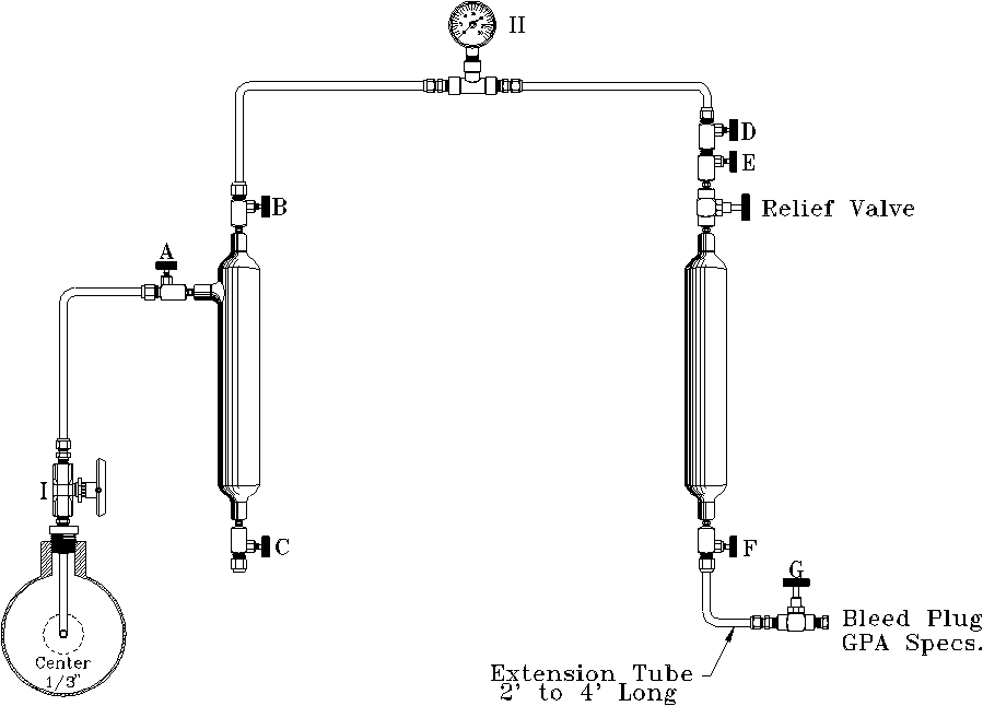
Attachment 1

G.P.A. FILL AND EMPTY METHOD
TYPICAL RECOMMENDED MANIFOLD HOOK-UP
I. Sample Probe
II. Sample Pressure Gauge (same as line pressure)
Steps to follow to draw sample:
- Open Valve 'I' to blow any accumulated foreign matter in probe or valve.
- Connect manifold to probe Valve 'I' (close Valve 'I').
- Open Valves 'A', 'B', 'D', 'E', and 'F'. Valves 'C' and 'G' remain closed.
- Open Valve 'I' to allow full pipeline pressure to fill complete manifold.
- Close Valve 'A' and open Valve 'G' to allow gas in the manifold to bleed to 0 psig.
- Close Valve 'G' and open Valve 'A' to allow pressure to build rapidly to full line pressure.
NOTE: Steps 4 through 6 should be repeated until all air has been eliminated from the system (3 to 5 times). - Open Valve 'A' quickly to fill manifold with full pipeline pressure. Close Valve 'A'.
- Open extension Valve 'G'. Allow pressure to bleed to 0 psig. Close Valve 'G'.
NOTE: If at any time liquids appear at Valve 'G', the sample should be discarded.
NOTE: Steps 7 and 8 constitute the fill and empty cycle and should be repeated as many times as required by your pipeline pressure and the chart below. Table 1 gives the minimum number of purges required to condition your sample cylinder (providing the sample cylinder is clean and dry).
Maximum Gas Pressure PSIG Number of Purge Cycles 15–30 13 30–60 8 60–90 6 90–150 5 150–500 4 Over 500 3 - At the completion of the proper number of purge cycles, close Valves 'E', 'F', and probe Valve 'I'. Bleed the pressure from the manifold and extension tube. Remove the sample cylinder from the manifold and check for leaks. Plug the valves. Fill out the proper sample tag and put the cylinder in a proper carrying case to be transported to the lab.
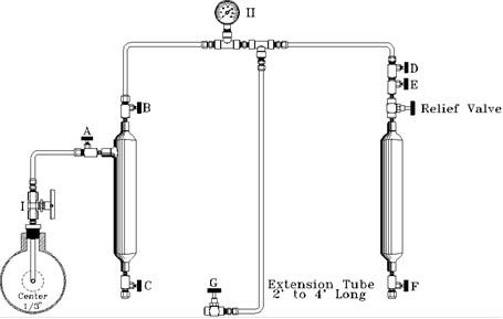
Attachment 2
G.P.A. CONTINUOUS PURGE METHOD
TYPICAL MANIFOLD HOOK-UP
Caution: This method should not be used on wet natural gas or gas over 400 psi.
I. Sample Probe
II. Sample Pressure Gauge (same as line pressure)
Steps to follow to draw sample:
- Open Valve 'I' to blow out any accumulated foreign matter in probe or valve (close Valve 'I').
- Connect sample manifold to probe Valve 'I'. All valves closed.
- Slowly open Valve 'I', and then slowly open in sequence Valves 'A', 'B', 'D', 'E', 'F', and 'G'.
NOTE: Valve 'G' must have flow plug installed. - Allow gas to flow through the manifold for a minimum of 3 minutes.
NOTE: That more time will be required if the sample cylinder has not been properly cleaned and dried.
NOTE: G.P.A. method should be consulted for unusual conditions. - After specified time, valves should be closed beginning with Valve 'G' and working toward the source valve, sequence 'G', 'F', 'E', 'D', 'B', 'A', and 'I'.
- Bleed pressure from manifold and remove sample cylinder.
- Check cylinder for leaks and plug valves.
- Fill out sample card and put cylinders in proper box for shipment.
Attachment 3
G.P.A. METHOD FOR TAKING A SPOT SAMPLE IN AN
EVACUATED CYLINDER OR STANDARD SAMPLE CYLINDER
FILLED WITH AN INERT GAS
- Evacuate a clean sample cylinder and plug valves.
- Open probe Valve 'I' to clean valve and probe of accumulated materials.
- Connect manifold to probe Valve 'I'.
- With all valves closed, attach sample cylinder to manifold.
NOTE: Check with a gauge to ensure sample cylinder is evacuated. - Open probe Valve 'I', 'A', and 'B'. All other valves closed.
NOTE: Sample gauge II will indicate pipeline pressure. - Close Valve 'A'.
- Open Valve 'G' on the extension tube.
NOTE: This will bleed manifold pressure to 0 psi.
NOTE: Steps 6 and 7 constitute a purge of the piping to the evacuated cylinder. This should be repeated as required by your pipeline pressure to ensure any air in the lines has been purged with gas. - Open Valve 'A' with Valve 'B' open, slowly open Valve 'D' and allow line pressure to fill sample cylinder.
- Close Valve 'D'. Close Valve 'I'. Open Valve 'G' to remove pressure from the sample manifold.
- Remove sample cylinder from manifold. Check for leaks, plug valves, fill out sample information, and put cylinder in an appropriate case for transportation.
Attachment 4

DRAWING A SPOT SAMPLE INTO A CONSTANT PRESSURE
(SLIDING PISTON) SAMPLE CYLINDER
To draw a spot sample into a constant pressure sample cylinder, the following procedure should be used.
Prior to going to the field, check these items:
- Has the cylinder been emptied, cleaned, and checked for leaks?
- Attach to the precharge Valve 'G', a supply of inert gas (N2), with Valve 'B' open, and fill the cylinder to 100 psi above line pressure. Close Valves 'G' and 'B'.
- Put the cylinder in a carrying case with the proper transport papers, and go to the field.
At the sample point:
- With an appropriate connector, connect Valve 'B' on the cylinder to the process connection 'I' (sample probe).
- Valves 'I', 'A', 'B', and purge valve are closed.
- Open Valve 'I'. Check the connections for leaks.
- Open Valve 'B'. This allows product to flow into the cylinder to the face of the piston.
- Purge: Close Valve 'I' with 'B' open, open 'A' (slowly). Bleed off the product in the cylinder.
- Close Valve 'A'.
- Open Valve 'I'.
- Close Valve 'I'.
- Open Valve 'A' (slowly).
- Close 'A'.
NOTE: By opening 'I' and 'A', you fill and empty the piping and cylinder to eliminate air or contaminants. If the pressure is above 500 psi, 3 to 5 purges will be adequate. Do not flow through with all valves open. This may cause retrograde condensation to occur.
To draw the sample after the purge:
- Open Valve 'I'.
- Open Valve 'B'. Valve 'A' remains closed. Product is now against the face of the piston.
- Slowly open Valve 'G'. Bleeding off the precharge from the back side of the piston will allow the process pressure to fill the sample container.
- When the indicator reaches 80%, close Valve 'G'. You now have 80% product, 20% precharge, and the cylinder may be transported.
To disconnect the cylinder from the process:
- Close Valve 'I' (probe valve) and Valve 'B'.
- Slowly open Valve 'A' to remove the pressure between the purge valve and cylinder inlet valve 'B'.
- Remove connection at Valve 'B', plug all the valves, fill out the paperwork, and put the cylinder in a carrying case for transportation.
Attachment 5

TYPICAL SAMPLE HOOK-UP OF CYLINDER
Note: Not recommended.
Sample taken by simply viewing into a convenient valve is not a proper means by which to take a representative sample of any type.
Attachment 6
