
Fundamentals of NGL Sampling Systems
The purpose of this paper is to discuss in depth systems we use as a standard to sample natural gas liquids, or NGL’s. Before we discuss the systems and methods used to sample these products, we must first clearly define what NGL’s are. NGL’s can be a combination of any fluid in liquid form that is taken from the pipeline under pressure. Typically, “NGL” refers mainly to ethane, propane, butanes, natural “gasolines” (pentanes) and condensates. Because of the broad range of products that can be claimed as NGL’s, there are many different approaches to the methods by which we sample them. The common thread among all NGL’s is that these products, in order to be maintained and properly sampled, require the use of specific sampling techniques unique to light liquid and NGL sampling.
To further expand on the sampling techniques used in NGL and light liquid sampling, we must first have a look at the current need for sampling systems in the NGL market and discuss why there is such a need for these systems. NGL’s are a production by product of the shale gas boom that is occurring across our country. Over the past few years the new developments in fracking techniques, has allowed many production companies to drill gas wells and produce large amounts of natural gas that traditionally was not available to us through other conventional methods. This large spike in natural gas surplus subsequently has driven the price of natural gas down, and caused some alarm amongst the production companies in the US market. During the last five years, a shift in the production methods and refinement process of natural gas has caused many of these producers to look at the benefit of drilling “liquid rich” shale formations. These “liquid rich” shale plays are notorious for producing higher amounts of NGL’s. With these NGL’s being more profitable than the falling natural gas prices, the push towards separating and selling these NGL’s has meant a tremendous increase in those companies’ profitability. Naturally, this increase in profitability has prompted the age old question of “how much do we have, and what exactly do we have”. This is where the importance of proper sampling and collection techniques becomes vital and necessary.
Implementation of proper sampling techniques is important in many areas of the oil and gas process. Delivery of oil and gas and the byproducts of those components to the marketplace prompt us to require sampling at many different stages of the process. For instance, liquid petroleum gas, commonly known as LPG’s are the most pure forms of NGL’s found in the market place. The refinement process of these components can be accomplished in several different ways. During the refinement process, these LPG’s are separated out so that they can be stored in individual storage tanks or sent down a pipeline to change hands. The separation process of these types of products is accomplished by several different methods within the refineries. In “lean oil” plant NGL recoveries we see a limitation of the amount of LPG’s that are recovered from the gas streams. Large amounts of butanes and propane can be extracted from the streams but generally we see only 15%-30% of the ethane inherent in the gas can be effectively extracted. This number is increased in refrigeration plants where propane is used to chill the gas. The percentage of ethane removed increases to above 75% and virtually 100% of the butanes and propanes are extracted. The most effective extraction of LPG’s in a refinery application is by means of cryogenic technology. This method, it should also be noted, is the most costly of the three to build. This method encompasses compressing the components and then sending them through an apparatus known as a turbo expander. This device uses a controlled drop in pressure to chill the products therefore causing the heavier components of the gas to fall out of the gas stream in a liquid form. Almost 90% of the ethane is removed by using this process. However effective these methods are, it remains in some processing plants, only methane is separated out of the group of components. The remaining mixture of components (ethane through pentanes) is left in the liquid stream and is often referred to as “Y-grade”. Another area where LPG production is found is in crude oil refineries. LPG’s are produced by fractionation of the crude oils into lighter hydrocarbons by a multitude of processes. The relationship sampling holds in these applications is important to realize and can greatly affect the profitability factor of each company involved. In LPG refinement applications, the sampling process is used to determine the liquid hydrocarbon content simply because there is no water due to the intensity of the process. By sampling in these applications, we can determine the mol percentage of the products, therefore realizing its market value.
Another application where we would see NGL sampling needs is in the separation of the gas stream in the production field or upstream of the gas processing plants. These separators are designed to drop out the liquid components of the gas stream by using gravity and kinetic energy of the flowing stream against the side of the vessel. The different components experience a level of separation where gas, liquid hydrocarbons and water will exist on different levels. Utilizing a series of valves and level detecting devices, these tanks will be emptied of the water and hydrocarbons. The water will be sent into one stream for disposal and the liquid hydrocarbons into another stream to be measured and then sent on to reach its intended use. This method, although inexact, is very useful and mostly cost effective in being able to separate the components coming in from the production well. In most cases during the operation of the separator dumping process, there often times can be water carryover experienced into the liquid hydrocarbon stream. This is most often experienced when the dumping of the much heavier NGL’s, such as condensate, occurs within the separator. In this case we look to a tool used in measurement that will enable us to check the content of the liquid hydrocarbon stream as it leaves the separator. Water content is a critical part of determining the value of these hydrocarbons during custody transfer. As in many crude oil applications, line conditioning when sampling these types of light liquids must be considered. A very useful method for preconditioning of the line is by introducing a static mixer into the stream prior to the sampling apparatus. The static mixer uses a series of blades engineered to create a homogenous mixture of the water and hydrocarbons. The mixer uses the flowing velocities of the stream to create turbulence. The resulting mixture is a representation of the entire flowing stream. An important factor that must be considered when using a static mixer is that the mixer must have adequate flow at the sample point to create the homogenous flow scenario. A second factor that greatly influences the resulting sample is the placement of the sample in the pipe run. The sampler must be placed in an area where the flow is adequate, but also there must be consideration as to whether or not there is inherent water traps located in the pipe run. If the sampler is located improperly near one of these trap areas, it could be detrimental to the results given by the sampler. Placing the sampler on a vertical run of pipe after the separator is an example of a good place where water traps will not be experienced. It should also be noted that the placement of the mixer in conjunction with the sampling pump is very important in the mixing process. This is mostly due to the rapid settling out of the water in these types of liquid hydrocarbons, and is important when sampling for water cut applications. It is important to note also that the sampler should be used in conjunction with a second measurement device such as a turbine, or ultrasonic meter. This will allow the operator to take sample grabs that will be proportional to the flow of product through the pipeline at any given time. Combining these two measurement tools allows us to firstly measure “how much” product is flowing in the pipeline as well as defining “what content” we have in the pipeline. This is the most accurate way to ensure that the sample is most representative of the composition of the flowing stream, and is the recommended practice for most applications. It is by using this method we can properly allocate back to where the products are being delivered from; ultimately having a tremendous monetary impact for the producer, customers, and land owners.
The first aspect of the system to discuss is, in order for the sampling of light liquid hydrocarbons to be representative of what is in the pipeline, we must ensure that the pressure in the pipeline or vessel is maintained at the condition that it exists while it is being sampled. There should be no reduction of pressure or the phase of the liquid could flash or change into a gaseous state. The best way to accomplish this is to use a dual cavity or constant pressure cylinder. This cylinder involves an internal piston which can be reciprocated with pressure by manipulation of valves on each end cap of the cylinder. The end caps are held by either tie rods or threads that secure the end caps. There are many features of these types of cylinders that promote both accuracy and safety all the while ensuring properly collecting an NGL sample. One of these features is an external indicator to show the location of the piston in the cylinder. The indicator can be a magnet style tracking device or a rod connected to the piston. It is important to know the fill level of the cylinder to allow for any expansion that could occur within the cylinder. Because these cylinders have the capacity to hold a constant pressure, the likelihood of expansion is minimized, but the fill indicator gives the technician a method of reassuring that the capacity of the cylinder remains at a constant level, and the sample phase has not changed. These cylinders also incorporate burst disc reliefs and optional relief valves to help support the safety functions of the cylinder. An example of a constant pressure cylinder is shown in Figure 4.
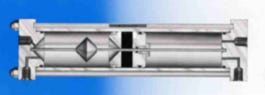
₄ Constant Pressure Cylinder with Gravity Type internal mixer
A second benefit to using a constant pressure or piston style cylinder is that often times a mixing element can be used internal to the cylinder. An example of a “gravity type” mixing element is shown in the above Figure 4. Prior to transferring sample from this cylinder or any other type of constant pressure cylinder, it is still very important to mix the sample prior to the transfer. This ensures that the content of the cylinder is homogenous and will be representative of the whole sample. The “sample side” of the cylinder will contain the mixing element, while the opposing side of the piston or the pre-charge side will not have a mixing element. To obtain a sample with this style cylinder, the first step is to open the valves on both ends of the cylinder releasing any pressure that could be in the cylinder. Second step is to connect the pre-charge side to either an inert gas or natural gas out of a pipeline. Third step is to introduce the pre-charge gas into the pre-charge side of the cylinder at a pressure that is greater than or equal to the light liquid process that is going to be sampled. This will force the piston over to the product end displacing all empty space or product that is present out of the cylinder. Fourth step is to connect the product side of the cylinder to the process that is to be sampled and introduce the product into the cylinder. If the cylinder contains a purge port (which is highly recommended) at this stage the product side of the cylinder should be purged to rid the cylinder of any previous sample or any ambient condition which could exist. At this point the cylinder is ready to receive the sample.
When pulling a product from the pipeline or a tank, there are two methods of sampling to consider. These two methods are spot sampling and composite sampling. A spot sample is a snap shot or one time sample of what is passing by in the pipeline or a tank at that given time, and it usually involves a probe in the process and a single cavity cylinder or a container. The process by which we take a spot sample can be as simple as following the operation of use with a constant pressure cylinder. Using this type of cylinder allows the technician a very good view into how much sample is being collected, and introduces a high safety factor into the equation. Spot samples can also be drawn with a single cavity cylinder; however, it is very important to remember that pressure changes can cause flashing of the sample and using the single cavity cylinder introduces this factor into the equation. It is also very important to remember that in using a single cavity cylinder to spot sample NGL’s, the proper set up is necessary and a cylinder with an outage tube must be used to allow the space needed for expansion.
A composite sample is many samples taken over a period of time. By using this method, the technician can obtain a very good representation of the whole batch. The two common methods used to obtain a composite sample are to take the sample bites proportional to flow in the pipeline, or to take the sample bites in accordance with time and over a designated time period. Either of these composite sampling methods is good and can provide you with improved accuracy over a spot sample by giving a better snap shot of the batch flowing over that time frame or batch. When considering composite sampling, there are several components that must be considered to pull the sample from the process with accuracy. The composite sampling system involves a sample pump, controller interconnected with a metering device, a cylinder and in some processes a conditioning device in the pipeline upstream of the sampling point.
With a composite sample you will have a sample pump to inject a preset volume per actuation of the pump into a cylinder. This pump will be controlled by a controller that is connected to a metering device that will give a pulse or signal in proportion to the flow of the process. The pump is usually a piston or diaphragm pump that is actuated by an electro pneumatic solenoid. The pump will be set up to have a hot or circulation loop to flow through the pumps’ sample chamber. The hot loop is set up to have a probe receiving product out of the pipeline ran through tubing to the pump and then returned to the process pipeline downstream of a device that will cause a pressure drop in the pipeline. This configuration is shown in Figure 1 using an orifice plate to create the differential pressure.

The pump can also be set up on a pitot type probe which is a probe with an outlet and return ports. The probe is configured to use the flow of the process pipeline to create a differential pressure between the two ports and will result in product circulating through the pumps’ body. More importantly, by using the hot loop, we can ensure a fresh sample is circulating through the sample pump resulting in a representative sample of what is in the pipeline. This is very important in NGL applications where slight variances in pressure and temperature can cause the product to flash and turn NGL’s into their gaseous state. Any liquid allowed to flash can cause the sample to become unrepresentative. In some instance it is necessary to insulate the tubing to keep the product from flashing once passed the pump and into the cylinder.
Another option to create this hot loop is to use a micro pump to create the circulation in the hot loop. The cylinder is then connected to the pump and each time the sample cycle begins the cylinder will be set up to receive the sample as described before. With some systems, there are large volume cylinders (up to five gallons) that are set up in a vertical configuration. These cylinders are usually stationary and are used as collection vessels to obtain a large enough volume of product being sampled so, at the end of the sample cycle, smaller cylinders of sample will be used to draw off a smaller size sample and sent to the respective buyer, seller and third party. These larger cylinders; as in most cylinder applications, will have a mixer to mix the product before the sample is drawn off into the smaller cylinders. The larger cylinders will also have a pre-charge gas tank that is filled with nitrogen that will be filled to about 100 PSI above the process line pressure. This will allow the product side of the cylinder to be filled and emptied without having to pressurize the pre-charge each time a sample cycle is started. The pressure will oscillate between the pre-charge end of the sample container and the nitrogen tank with little pressure increase or decrease due to the volume of gas in the nitrogen tank.
Another method to take a composite sample without having the benefit of a hot loop is to use an inline pump. These pumps have the sample chamber located in the flow of the pipeline and are a very effective way to get a representative sample of what is in the pipeline. An example of this pump configuration is show in Figure 2.
₂ NGL composite sampling system using hot/fast loop

Both of these methods in the diagrams show a way to get a sample without the benefit of conditioning the process line upstream of the sample point. This type of configuration is appropriate to use if you are sampling light liquid hydrocarbons in a gas plant or refinery situation where water is not a factor in the sampling process. If it is necessary to see if water is present in the liquid stream, you should use a form of mixer upstream of the sampling point. The pump should be of the type that is isokinetic where the flow of the pipeline is flowing through the sample chamber located in the pipeline downstream of the conditioning device. An example of this type of set up is shown in Figure 3.

Also when water could be present, the sample should be drawn off into the smaller sample cylinder that should have a mixer of the same type that is used in the larger cylinders. This type of mixer is referred to as a vortex mixer. There is a “T” handle on the end and with a reciprocating motion the cylinder mixes the internal components with the water before the contents are drawn off for the lab analysis. The moving of the “T” handle moves a paddle through the product mixing the water with the liquid hydrocarbons resulting in a representative sample to be extracted from the cylinder. An example of this style cylinder is shown in Figure 5.
₃ NGL composite sampling system using inline pump/sampler
₄ NGL composite sampling system using inline pump/sampler and static inline mixer

In situations where water can be present in the liquid hydrocarbons, it is recommended to use an inline type sample pump. This is mainly due to the gravity of the light liquid hydrocarbon and its relation to the water in the system. It has been shown that the water in these applications will drop out rapidly from a flowing stream and settle out in low areas. In these situations, it is not recommended to use a by-pass or hot loop style system because of the potential for drop out resulting in misstated water cuts. This is especially true where there is not sufficient velocity in the hot loop to push the water through the hot loop and back into the pipeline. A mixer must be carefully placed close to the sample point to ensure that the correct mixture is achieved and the sample taken can be representative.
Another important consideration for composite sampling is to be sure at the end of a sample cycle the correct amount of sample has been taken. When working with a compositor, it is necessary to do batch calculations to determine how many sample pump actuations would be required to fill the size cylinder you have over the batch period. For example, if you have a 500 cc cylinder, and you want to fill it to eighty percent, you would need to displace 400cc. If the pump injects .5 cc per actuation, you would need 800 actuations to fill the cylinder. Therefore you would take the volume that you are sampling for the time period that you are sampling and divide that by your number of actuations. An example of this would be a 40,000 total barrel batch in conjunction with the .5cc pump and a 500cc cylinder. By using the provided calculation, you would have a sample pump actuations every 50 barrels that flows by the sample point.
It has been proven in many laboratories that using the proper sampling technique and sampling system can provide accurate results. The importance of utilizing the proper equipment can be effective in obtaining these accurate results. By using techniques including constant pressure cylinders for both transportation and collection, we can collect NGL’s in a fashion that ensures the sample will not flash. Using constant pressure equipment can also add an additional safety factor for the technician which cannot be understated. Ultimately, the process by which the sample is taken; whether it is a spot or composite sample, can provide a tremendous monetary advantage for the company.
₅ Constant Pressure cylinder with vortex mixer and “T” handle